Thursday, January 16, 2020

ACI Endpoint Learning and Traffic Forwarding

Agenda
The following topics will be discussed
  1. Introduction
  2. Endpoint Learning
  3. ACI Fabric Traffic Forwarding
  4. References
Introduction
In this post we will talk about  how endpoints are learned  and how traffic is forwarded in ACI fabric.
Understanding how Endpoints are learned and how traffic is forwarded can greatly simplify  troubleshooting process

Endpoint Learning

ACI Endpoint
  • An Endpoint consists of one MAC address and zero or more IP addresses
  •  IP address is always /32
  •  Each endpoint represents a single networking device
In ACI, there are two types of Endpoints
  • Local endpoints for a leaf reside directly on that leaf, these are directly attached network devices.
  • Remote endpoints for a leaf reside on a remote leaf


  • Both local and remote endpoints are learned from the data plane
  • Local endpoints are the main source of endpoint information for the entire Cisco ACI fabric.
  • Leaf learns Endpoints (either MAC or/and IP) as local
  • Leaf reports local Endpoints to Spine via COOP process
  • Spine stores these in COOP DB and synchronize with other Spines
  • Spine doesn’t push COOP DB entries to each Leaf. It just receives and stores.
  • Remote Endpoints are stored on each Leaf nodes as cache. This is not reported to Spine COOP.
Forwarding tables
In Cisco ACI 3 tables are used to maintain the network addresses of external devices, but these tables are used in a different way than used in traditional network as shown in the following table.


1. RIB Table is the VFR routing table, also known as LPM (Longest Prefix Table). It is populated with:
  •     Internal fabric subnets (non /32 only), these are bridge domain subnets
  •     External fabric routes (/32 and non /32)
  •     Static routes (/32 and non /32)
  •     Bridge domain SVI IP address
2. Endpoint Table stores endpoints MAC and IP addresses (/32 only). This table has two components
  • LST (Local Station Table): This table contains local endpoints. This table is populated upon discovery of an endpoint.
  • GST (Global Station Table): This is the cache table on the leaf node containing the remote endpoint information that has been learned through active conversations through the fabric.
 3. ARP Table stores IP to MAC relationship for L3Out. Cisco ACI uses ARP to resolve next-hop IP and MAC relationships to reach the prefixes behind external routers

How Endpoint Endpoints are learned
Cisco ACI learns MAC and IP addresses in hardware by looking at the packet source MAC address and source IP address in the data plane instead of relying on ARP to obtain a next-hop MAC address for IP addresses. 

This approach reduces the amount of resources needed to process and generate ARP traffic. It also allows detection of IP address and MAC address movement without the need to wait for GARP as long as some traffic is sent from the new host.

Cisco ACI leaf learns source IP addresses only if unicast routing is enabled on the bridge domain. If unicast routing is not enabled, only source MAC addresses are learnt, and the Leaf performs only L2 switching

Local Endpoint Learning 
  • Cisco ACI learns the MAC (and IP) address as a local endpoint when a packet comes into a Cisco ACI leaf switch from its front-panel ports.
  • Cisco ACI Leaf always learn source MAC address of the received packet
  • Cisco ACI Leaf learn source IP address only if the received packet is an ARP packet or  a packet that is to be routed (packet destined to SVI MAC) 
Remote Endpoint Learning
Cisco ACI learns the MAC (or IP) address as a remote endpoint when a packet comes into a Cisco ACI leaf switch from a remote leaf switch through a spine switch.

When a packet is sent from one leaf to another leaf, Cisco ACI encapsulates the original packet with an outer header representing the source and destination leaf Tunnel Endpoint (TEP) and the Virtual Extensible LAN (VXLAN) header, which contains the bridge domain VNID or VRF VNID. 

Packets that are switched contain bridge domain VNID. Packets that are routed contain VRF VNID. 

  • Cisco ACI Leaf learn source MAC address of the received packet from spine switch if VXLAN field contains bridge domain VNID.
  • Cisco ACI Leaf learn source IP address of the received packet from spine switch if VXLAN field contains VRF VNID.
Endpoint mouvement and bounce entries
The following steps describes how the forwarding tables are updated when an endpoint moves between two Cisco ACI leaf switches following a failover event or a virtual machine migration in a hypervisor environment.


  a) At the initial state, the endpoint tables reflect the state of the network


b) When the endpoint A moves to Leaf 103
  1. Leaf 103 learn about A, when A sends its first packet
  2. Leaf 103 updates the COOP database on the spine switches with its new local endpoint
  3. If the COOP database has already learned the same endpoint from another leaf, COOP will recognize this event as an endpoint move and report this move to the original leaf that contained the old endpoint information.
  4. The old leaf that receives this notification will delete its old endpoint entry and create a bounce entry, which will point to the new leaf. A bounce entry is basically a remote endpoint created by COOP communication instead of data-plane learning.
  5. Leaf 104 still contains the old location information of endpoint A


c) B sends a packet to A
  1. As B has not updated yet its Endpoint table about the Endpoint A location, the packet is sent to Leaf 101/Leaf 102
  2. Because of Bounce bit set for endpoint A, Leaf 101/Leaf 102 bounces the received packet to Leaf 103.
  3. Leaf 103 update its endpoint table with Endpoint B information

d) A replies to B
  1. Leaf 104 update its endpoint table with Endpoint A information

ACI Fabric Traffic Forwarding
L2 switched traffic 


At the initial state
  • Endpoint tables on Leaf 101 and Leaf 106 are empty
  • COOP tables on spine switches are empty
  • VRF table contains the following information
                - 192.168.1.254/24: BD SVI

                - 192.168.1.0/24: bridge domain subnet

The following steps described traffic flow from host A to host B

1. Host A sends an ARP request to resolve host B IP to MAC addresses 

2. Leaf 101 learn host A source MAC and IP addresses, and notify this information to spine switches through COOP (Council Of Oracle Protocol) 

3. One of the following events can happen depending of the setting of ARP Flood option in bridge domain configuration 
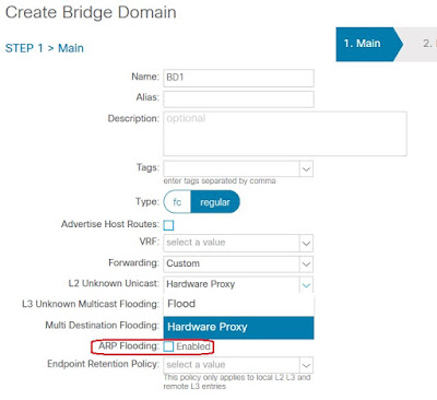
  • If ARP Flooding option is enabled, leaf 101 flood the ARP request inside the bridge domain
  • If ARP Flooding option is disabled and Leaf 101 has information about host B IP address. Leaf 101 will send the ARP request to destination Leaf based on ARP target IP field.
  • If ARP Flooding option is disabled and Leaf 101 has no information about host B IP address disabled, leaf 101 sends the ARP packet to Spine switches. if spine switch has no information about host B IP address either, it drops the ARP packet and generate a broadcast ARP request form the bridge domain SVI to resolve host B IP to MAC addresses. This process is called ARP Gleaning

4 Host B sends ARP reply to the spine switch. Remember this is a reply to the request generated by the spine

5. Leaf 106 learns host B MAC and IP addresses and notify this information to spine switches

6. Host A sends a second ARP request to resolve host B IP to MAC addresses

7. As leaf 101 doesn’t know host B IP address (ARP target IP address) yet, depending of the setting of ARP Flooding option, it either flood or send the request to the spine. In either case, the ARP request will find its way to host B

8. Host B Sends ARP reply to Leaf 101

9. Leaf 101 learns host B MAC and IP addresses as a remote endpoint and store this information in its endpoint table

10. Host A sends an IP packet to host B

11. Leaf 101 lookup destination MAC address in its endpoint table, a match is found, then it determines if a contract is necessary to forward the frame - if so, it will need to look at the L3/4 contents of the packet to determine if a contract exists.

In case where host A has host B in its ARP cache, and leaf 101 has not this information in its endpoint table, no ARP request will be sent by host A. What Leaf 101 will do in the case it receives an IP packet form host A will depend on the setting of L2 Unknown Unicast option in bridge domain configuration
  1. If this option is set to Hardware Proxy, leaf 101 send the packet to the spine switches anycast address. If the spine switch doesn’t have information about host B, it drops the packet. This process is called spine-proxy
  2. If this option is set to Flood, leaf 101 food the packet inside the bridge domain
L3 Routed Traffic

  1. Host A sends an IP packet to host B. the Destination MAC address in the packet is the bridge domain SVI MAC address
  2. Leaf 101 receives the packet, learns host A MAC and IP addresses
  3. Leaf 101 lookup destination MAC address in its endpoint table, a match with BD SVI MAC address is found, so this is a packet to be routed
  4. Leaf 101 lookup Longest Prefix Match for IP destination address in its VRF table.
  • If a match is found, and the match is an external subnet, the packet is routed to the leaf where VRF L3Out is attached, the policy is applied there based on the contacts applied to the subnet" defined in the Networks section of the L3 Out.
  • If a match is found, and the match is a fabric internal subnet (remember, all BDs subnets are in the VRF table), leaf 101 lookup host B /32 IP address in the endpoint table
  1. If a /32 match is found, it determines the EPG of the destination and apply the policy, then forward the packet to destination Leaf if the packet is permitted
  2. If no /32 match is found, the packet is sent to the spine. If the spine doesn’t know /32 destination either, it drops the packet and starts ARP Gleaning process for host B /32 IP address
  • If no match is found, the packet is dropped
References
Following are some useful documents used as a reference for this post:

Sunday, January 5, 2020

Introduction to Cisco Hyperflex

Agenda

The following topics will be discussed
  1.   Introduction
  2.   Cisco Hyperflex
  3.   System Components
  4.   Topology Overview
  5.   HyperFlex Data Plateform (HXDP)
  6.   Logical Network Design ( vMware Use Case)
  7.   Installation
  8.   Management
  9.   References

Introduction

HyperConverce Infrastructure (HCI) has the following characteristics:
  • Combine compute, storage and the network in one platform
  • Unified Management
  • Distributed Direct-Attached Storage (DAS)
Cisco Hyperflex

HyperFlex (HX) is Cisco’s move into the hyperconvergence space with a new product line designed for hyperconverged environments.

Cisco HyperFlex solution combines compute, storage and the network in one platform.

The platform is built on existing UCS components and a new storage component. The servers used in the solution are based on the existing Cisco UCS product line. Networking is based on the Cisco UCS Fabric interconnects switches. The new storage component in Cisco’s platform is called the Cisco HyperFlex HX Data Platform, which is based on Springpath technology.

Cisco HX supports multiple hypervisors, such as VMware ESXi, Microsoft Hyper-V, and KVM (roadmap); it also supports virtualization through containers.


System Components

Cisco HyperFlex solution consists of: 
  • Nodes: these are converged nodes ( compute and storage), or compute only nodes that forms a cluster
  • Fabric Interconnect switchs (FI): these are switchs that interconnects nodes, and interconnects nodes to customer LAN/WAN
Cisco HyperFlex nodes

Cisco HyperFlex nodes comes in different flavors which are:
  • HyperFlex Hybrid Nodes
  • HyperFlex All-Flash Nodes
  • HyperFlex All-NVMe Nodes
  • HyperFlex Edge Nodes
  • HyperFlex Compute-Only Nodes
Up to date list and detailed specifications can be found on the following Link
  • HX hybrid nodes Converged nodes, use serial-attached SCSI (SAS), serial advanced technology attachment (SATA) drives, and SAS self-encrypting drives (SED) for capacity. The nodes use additional SSD drives for caching and an SSD drive for system/log.
  • HX all-flash nodes Converged nodes, use fast SSD drives and SSD SED drives for capacity. The nodes use additional SSD drives or NVMe drives for caching and an SSD drive for system/log.
  • HX all-flash nodes Converged nodes, use NVMe SSD drives for capacity. The nodes use additional NVMe drives for caching and write-logging
  • Edge Nodes: Converged nodes, Hybrid node targeted toward remote office/branch office (ROBO) application. 
  • Compute-Only nodes: These nodes contribute to memory and CPU but do not to capacity. 
All nodes supports Virtual Interface Card a next-generation converged network adapter (CNA) that enables a policy-based, stateless, agile server infrastructure that presents up to 256 virtual  PCIe standards-compliant interfaces to the host that is dynamically configured as either network interface cards (NICs) or Host Bus Adapters (HBAs).


Fabric Interconnects 
  • Fabric Interconnects (FI) are deployed in pairs
  • The two units operate as a management cluster, while forming two separate network fabrics, referred to as the A side and B side fabrics. Therefore, many design elements will refer to FI A or FI B, alternatively called fabric A or fabric B.
  • Both Fabric Interconnects are active at all times, passing data on both network fabrics for a redundant and highly available configuration
  • Management services, including Cisco UCS Manager, are also provided by the two FIs but in a clustered manner, where one FI is the primary, and one is secondary, with a roaming clustered IP address. This primary/secondary relationship is only for the management cluster, and has no effect on data transmission.
Topology Overview
  • The Cisco HyperFlex system is composed of a pair of Cisco UCS Fabric Interconnects along with up to 64 nodes (32 HyperFlex converged nodes + 32 Compute-only nodes) per cluster.
  • In the edge node configuration, Cisco Hyperflex systme supports up to 4 Edge converged  nodes. the use of  Fabric Interconnect switch is not required, any L2 switch could be used
  • The two Fabric Interconnects both connect to each node.
  • Upstream network connections, also referred to as “northbound” network connections are made from the Fabric Interconnects to the customer datacenter


                                                                       Hyperflex nodes

HyperFlex Data Platform

The engine that runs Cisco’s HyperFlex is its Cisco HX Data Platform (HXDP).

The HXDP is designed to run in conjunction with a variety of virtualized operating systems such VMware’s ESXi, Microsoft Hyper-V, Kernel-based virtual machine (KVM), and others.

Currently, Cisco supports ESXi, Microsoft Windows Server 2016 Hyper-V, and Docker containers.

HyperFlex Data Platform Controller (DPC)


  • Runs as a VM on top of Hypervisor in each Converged node and implements a scale-out distributed file system using the cluster’s shared pool of SSD cache and SSD/HDD capacity drives.
  • Implement log-structured file system that uses a caching layer in SSD drives to accelerate read requests and write responses, and a persistence layer implemented with HDDs or SSD
  • DPCs communicate with each other over the network fabric via high-speed links such as 10 GE or 40 GE depending on the specific underlying fabric interconnect.
  • Handles all of the data service’s functions such as data distribution, replication, deduplication, compression, and so on.
  • Creates the logical datastores, which are the shared pool of storage resources.
  • The hypervisor itself does not have knowledge of the physical drives. Any visibility to storage that the hypervisor needs is presented to the hypervisor via the DPC itself.
  • DPC integrates with the hypervisor using two preinstalled drivers: 
  1. IOvisor is used to stripe the I/O across all nodes. All the I/O toward the file system, whether  on the local node or remote node goes through the IOvisor.
  2.  An integration driver for specific integration with the particular hypervisor. the role of this agent is to offload some of the advanced storage functionality, such as snapshots, cloning, and thin provisioning to the storage arrays
  • The compute-only nodes have a lightweight controller VM to run the IOvisor
  • DPC uses PCI/PCIe pass-through to have direct ownership of the storage disks. DPC creates the logical datastores, which are the shared pool of storage resources.
Dynamic Data Distribution
  • HX uses a highly distributed approach leveraging all cache SSDs as one giant cache tier. All cache from all the nodes is leveraged for fast read/write. Similarly, HX uses all HDDs as one giant capacity tier. HX distributed approach uses HX DPC from multiple nodes.
  • If multiple VMs in the same node put stress on the local controller, the local controller engages other controllers from other nodes to share the load.
  • Data is striped across all nodes
  • A file or object such as a VMDK is broken in smaller chunks called a stripe unit, and these stripe units are put on all nodes in the cluster.

Data Protection With Replication
  • Replication of the data over multiple nodes. protect the cluster from disk or node failure.
  • The policy for the number of duplicate copies of each storage block is chosen during cluster setup, and is referred to as the replication factor (RF).
  • HX has a default replication factor (RF) of 3, which indicates that for every I/O write that is committed, two other replica copies exist in separate locations.
  • In case of a disk failure, the data is recaptured from the remaining disks or nodes.
  • If a node fails, data strip units are still available on othe nodes
  • The VMs that were running on a failed node are redistributed to other nodes using VM high availability, and the VM has access to their data


Inline Compression and deduplication
  • Always On, high-performance inline deduplication/compression on data sets to save disk space.
  • Deduplicated and compressed are performed when data is destaged to a capacity disk
  • Less CPU intensive

Data Rebalancing
  • Rebalancing is a nondisruptive online process that occurs in both the caching and persistent layers.
  • When a new node is added to the cluster, the rebalancing engine distributes existing data to the new node and helps ensure that all nodes in the cluster are used uniformly from capacity and performance perspectives.
  • If a node fails or is removed from the cluster, the rebalancing engine rebuilds and distributes copies of the data from the failed or removed node to available nodes in the clusters.

Logical Networ Design ( vWmare hypervisor use case)

Logical Zones

The Cisco HyperFlex system has communication pathways that fall into four defined zones.
  • Management Zone: This zone comprises the connections needed to manage the physical hardware, the hypervisor hosts, and the storage platform controller virtual machines (SCVM).
  • VM Zone: This zone comprises the connections needed to service network IO to the guest VMs that will run inside the HyperFlex system. This zone typically contains multiple VLANs that are trunked to the Cisco UCS Fabric Interconnects via the network uplinks, and tagged with 802.1Q VLAN IDs.
  • Storage Zone: This zone comprises the connections used by the Cisco HX Data Platform software, ESXi hosts, and the storage controller VMs to service the HX Distributed Data Filesystem.
  • VMotion Zone: This zone comprises the connections used by the ESXi hosts to enable vMotion of the guest VMs from host to host.
Virtual switches

HyperFlex Installer automatically create virtual switchs listed in the following table


VLANs

In Cisco HyperFlex system configuration, multiple VLANs to the UCS domain have to be carried from the upstream LAN. these VLANs are defined  in the UCSM configuration tab of HyperFlex Installer


Installation

The following 3 components are required to install Hyperflex
  • External vCenter server: to manage HyperFlex ESXi and HyperFlex system through Web client plugin. 
  • HX Installer: used to install HyperFlex and came as an OVA installed on either vMware ESX or vMware Workstation
  • DNS/NTP server: NTP is an absolute requierment


Fellow the bellow steps to install Hyperflex
  1. Use Consol port to provide Fabric Interconnect switches initial configuration (admin password, IP addressing, DNS, Domain name
  2. Use UCSM to install Fabric Interconnect; NTP, Uplink Ports (Connected to ustomerNetwork), Server Ports (Connected to HyperFlex Servers), Server Discovery
  3. Deploy HyperFlex Installer OVA
  4. Connect to Hyperflex Installer by browsing to Hyperflex Installer IP Address
  5. Choose "Cluster Creation with HyperFlex (FI)" workflow to create HyperFlex Cluster.
The workflow will guide you through the process of setting up your cluster. It will configure Cisco UCS policies, templates, service profiles, and settings, as well as assigning IP addresses to the HX servers that come from the factory with ESXi hypervisor software preinstalled. 

The installer will load the HyperFlex controller VMs and software on the nodes, add the nodesto the vCenter cluster, then finally create the HyperFlex cluster and distributed filesystem. All of processes can be completed via a single workflow from the HyperFlex Installer webpage


Mangement

HyperFlex can be managed through the following management tools:
1.     HyperFlex Connect
2.     vCenter Web Client Plugin

HyperFlex Connect


After the installation completes, HyperFlex system can be managed through HyperFlex Connect tool.

HyperFlex Connect is the new, easy to use, and powerful primary management tool for HyperFlex clusters. HyperFlex Connect is an HTML5 web-based GUI tool which runs on all of the HX nodes, and is accessible via the cluster management IP address. 

To manage the HyperFlex cluster using HyperFlex Connect, complete the following steps:
  1. Using a web browser, open the HyperFlex cluster’s management IP address via HTTPS
  2. Enter the username, and the corresponding password.
  3. Click Login.
  4. The Dashboard view will be shown after a successful login.


vCenter Web Client Plugin

The Cisco HyperFlex vCenter Web Client Plugin is installed by the HyperFlex installer to the specified vCenter server or vCenter appliance.

The plugin is accessed as part of the vCenter Web Client (Flash) interface, and is a secondary tool used to monitor and configure the HyperFlex cluster.

This plugin is not integrated into the new vCenter 6.5 HTML5 vSphere Client. In order to manage a HyperFlex cluster via an HTML5 interface, i.e. without the Adobe Flash requirement, use the new HyperFlex Connect management tool.

To manage the HyperFlex cluster using the vCenter Web Client Plugin, complete the following steps:

      1. Open the vCenter Web Client, and login with admin rights.

      2. In the home pane, from the home screen click vCenter Inventory Lists.


      3. In the Navigator pane, click Cisco HX Data Platform.


      4. In the Navigator pane, choose the HyperFlex cluster you want to manage and click the name.


References

Following are some useful documents used as a reference for this post:


Friday, December 6, 2019

ACI L3Out

Agenda

The following topics will be discussed

          1. Introduction

          2. L3Out Routing

          3. External EPG and Contract

          4. L3Out Configuration Details

          5. Transit Routing

Introduction

L3Out is an ACI managed Object used to connect ACI Fabric to external L3 networks. Every VRF in ACI Fabric that is to be connected to a L3 external domain requires one or more L3out.

The following diagram shows the interdependent objects of a L3Out (l3extOut) object in the ACI policy model hierarchy


L3Out Routing


Following are L3Out routing characteristics: 
  • L3Out supports Static, OSPF, EIGRP and BGP routing protocols
  • Leaf switch where L3Out is implemented is designated as Border Leaf Switche
  • Within the Cisco ACI fabric, multiprotocol BGP (MP-BGP) is implemented between leaf and spine switches to propagate external routes within the fabric. Leaf and spine switches are in one single BGP autonomous system (AS).
  • External routes of a given VRF instance learnt by Border Leaf on L3Out are redistributed to an MP-BGP address family (VPNv4 or VPNv6).
  • MP-BGP maintains a separate BGP routing table for each VRF instance.
  • Within MP-BGP, the border leaf switch advertises routes to a spine switch, which is a BGP route reflector. The routes are then propagated to all the leaf switches where the VRF instances are instantiated.
External EPG and Contract

At least one external EPG will be required for each configured L3Out. This external EPG is associated to L3Out VRF, and it represents the external networks. 

For VRF’s internal EPGs to be able to communication with external networks, one of the following options must be in place
  • A contract must exist between Internal EPG and External EPG
  • Include VRF’s EPG and the external EPG in a Preferred Group
  • Configure VRF’s Policy Control Enforcement Preference as Unenforced
L3out Configuration Details

The following figure shows the Topology being used to demonstrate L3out configuration

ACI Constructs that will be used are depicted in the following figure

The IP Addressing plan used is illustrated in the following table:

The following table lists the steps to fellow for L3out configuration


1. Create Attachable Access Entity Profile (AAEP)

From Fabric > Access Policies > Policies > Global, Right click on Attachable Access Entity Profiles to create an AAEP named TEST_AAEP


2. Create VLAN Pool


According to cisco documentation, this step is optional and is necessary only if an SVI will be used as a layer 3 interface for L3Out. 

From Fabric > Access Policies > Pools, Right click on VLAN to create a VLAN Pool named TEST_VLAN_Pool


3. Create External Routed Domain


 AAEP and VLAN Pool previously created will be assciated with External Routed Domain  

From Fabric > Access Policies > Physical and External Domains, Right click on External Routed Domain to create a L3 Domain named TEST_L3_Domain


4.  Create Interface Policy Group

This is the Policy Group that will be applied to the L3 Interfaces. Different interface policies (CDP, Speed…), including AAEP created previously, will be assigned to this Policy Group,

From Fabric > Access Policies > Interfaces > Leaf Interfaces > Policy Groups, Right click on Leaf Access Port to create an Access Interface policy Group and assign AAEP and Interface Policies previsiouly created

5. Create Leaf Interface Profile

The L3 interface (E1/1) and the Policy Group previously created will be assigned to the Interface Selector that will be added to this Interface Profile.

From Fabric > Access Policies > Interfaces > Leaf Interfaces, Right click on Profiles to create an Interface Profile

Click on the ‘+’ sign to add an Interface Selector


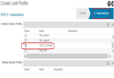
6. Create Leaf Switch Profile   


Border Leaf Switches 101,102 and the Interface Profile previously created will be assigned to the Switch Profile.

From Fabric >Access Policies > Switches > Leaf Switches, Right click on Profiles to create an Leaf Switch Profile.

Click on the ‘+’ sign to associate the Interface Selector, previsiouly created, to the switch Profile

7. Configure MP-BGP


Routes learned by Border Leafs trough L3Out will be distributed in the Fabric by MP-BGP routing protocol.

The Fabric will be in one BGP AS and two Spine switches will be configured as BGP Route Reflector

From System > System Settings > BGP Route Reflector, Configure BGP Route Reflector


8. Create Tenant


Click on Add Tenant to add TEST_TNT


9. Create VRFs


From Tenant >Tenant Name > Networking, Right click on VRFs to create VRF1. Uncheck Create A Bridge Domain option, Bridge Domain will be created later


Repeat this operation to create VRF2

10. Create Bridge Domains


From Tenant > Tenant Name > Networking, Right click on Bridge Domains to create bridge domain BD1. Assign VRF1 to BD1


Click on Next to create BD1 Subnet
  • Configure the Gateway IP address on BD1. This will be the Endpoint’s gateway
  • Check Advertised Externally option, this will allow BD1 subnet to be advertised through L3 Out

Repeat this operation for the other bridge domains BD2, BD3 and BD4


11. Create Application Profile


From TEST_TNT, right click on Application Profile


12. Create EPGs


From TEST_TNT > Application Profiles, right click on TEST_ApProfile to create Apllication EPGs


13. Create External Routed Networks (L3Out)


Despite each VRF is connected to R1 with two Sub Interfaces, since each VRF is connected to the same router with the same policy, only one L3Out per VRF is needed

From Tenant > TEST_TNT > Networking, Right click on External Routed Networks to create L3Out for VRF1.
  • OSPF routing protocol will be enabled and configured
  • Assign VRF1 and TEST_L3_Domain previously created to this L3Out
  • Check Route Control Enforcement Import option,  this will ensure external routes to be imported into VRF1 routing table


Click on Next then Finish

Repeat this operation to create VRF2 L3Out

14. Create Logical Node Profile


Logical Node Profile will be created for VRF1 and VRF2. The procedure bellow shows how to create Node Profile to associate Border Leaf (101 and 102) with VRF1 L3Out .

From Tenant > TEST_TNT > Networking > External Routed Networks > VRF1_L3Out, Right click on Logical Node Profiles to create Node Profile for VRF1 L3Out


Click on the ‘+’ sign, at the right to Nodes, to configure the Border Leaf switch (101) where this L3Out will associated; Also provide Border Leaf Router ID, the click on OK


Repeat this operation to configure Border Leaf switch (102) where the second VRF1 L3Out is associated; Also provide Border Leaf Router ID, the click on OK.

The figure bellow shows two nodes (101, 102) have been associated to VRF1_L3Out


Click on Submit 


15. Create Logical Interface Profile


From Tenant > TEST_TNT > Networking > External Routed Networks > VRF1_L3Out > Logical Node Profile > VRF1_L3Out_NdProfile, Right click on Logical Interface Profiles to create Interface Profile for VRF1 L3Out


Click on Next, to configure OSPF, BFD ad HSRP profiles


Click on Next to associate Routed Interfaces, Routed Sub-interface or SVI to L3Out. In this setup,
Routed Sub-interfaces will be used.


Click on the ‘+’ sign to add Sub-Interfaces


Click OK, and repeat the operation for the Sub-Interface on Leaf node 102

Click on OK, the Finish 

Repeat this operation to create and configure Interface Profile for VRF2 L3Out


16. Create External EPG


From Tenant > TEST_TNT > Networking > External Routed Networks > VRF1_L3Out, Right click on Networks to create External EPG for VRF1 L3Out


Click on the ‘+’ sign to configure external subnet for EPG.

  • External Subnets for the External EPG option (Checked by default) is much like an ACL, it defines which network is being assigned to this external EPG. An internal EPG can communicate only with this subnet (Provided, a contract is in place). 
    In the above configuration, any external subnet is assigned to this external EPG
Click on OK then on Finish

Repeat this operation to configure External EPG for VRF2 L3Out

17. Create Contract


From Tenant > TEST_TNT > Contracts, right click on Standard to create a contract to allow HTTP traffic
  
Click on ‘+’ sign to add Subject that allow HTTP traffic


Click on Submit


18. Assign Contract to EPGs


The contract created will be
  • Assigned to External EPG as Provided
  • Assigned to internal EPGs as Consumer
This will allow HTTP traffic-initiated form Internal EPGs to External Networks

In Tenant TEST_TNT navigate to VRF1_Ext_EPG. from policy > Contracts > Provided Contracts, click on ‘+’ sign to add the contract as Provided to External EPG


From TEST_TNT > Application Profiles > TEST_ApProfile > Application EPGs > EPG1, right click on Contracts to add the contract as consumed for EPG1.


From TEST_TNT >Application Profiles >TEST_ApProfile >Application EPGs > EPG2, right click on Contracts to add the contract as consumed for EPG2.


Repeat this operation to add TEST_Contract to VRF2_Ext_EPG, EPG3 and EPG4

Transit Routing

By default, routes learned from one L3Out are not redistributed to another L3Out, meaning transit routing is not enabled on ACI fabric.

Back to our setup, to redistribute routes learned from VRF1_L3Out to VRF2_L3Out we have to check some checkboxes in VRF1_Ext_EPG Create subnet configuration page.


In addition to External Subnets for the External EPG option, the following options have to be enabled:

  • Export Route Control Subnet option allows subnets, defined in IP Address (0.0.0.0/0 means any subnet), learned from VRF1_L3Out to be redistributed to VRF2_L3Out.
  • Aggregate Export option is only available if
                -  0.0.0.0/0 is configured as subnet


                -  Export Route Control Subnet is enabled

          Quote from Cisco APIC Online Help:
The same configuration has to be performed, in VRF2_Ext_EPG Create subnet configuration page, to export VRF2_L3Out routes to VRF1_L3Out.

Also, a contract must be configured between external EPGs, VRF1_Ext_EPG and VRF2_Ext_EPG, to allow communication between extenal hosts