Agenda
The following topics will be discussed
1. Introduction
2. L3Out Routing
3. External EPG and Contract
4. L3Out Configuration Details
The following topics will be discussed
1. Introduction
2. L3Out Routing
3. External EPG and Contract
4. L3Out Configuration Details
5. Transit
Routing
Introduction
Introduction
The following diagram shows the interdependent objects of a L3Out (l3extOut) object in the ACI policy model hierarchy
L3Out Routing
Following are L3Out routing characteristics:
- L3Out supports Static, OSPF, EIGRP and BGP routing protocols
- Leaf switch where L3Out is implemented is designated as Border Leaf Switche
- Within the Cisco ACI fabric, multiprotocol BGP (MP-BGP) is implemented between leaf and spine switches to propagate external routes within the fabric. Leaf and spine switches are in one single BGP autonomous system (AS).
- External routes of a given VRF instance learnt by Border Leaf on L3Out are redistributed to an MP-BGP address family (VPNv4 or VPNv6).
- MP-BGP maintains a separate BGP routing table for each VRF instance.
- Within MP-BGP, the border leaf switch advertises routes to a spine switch, which is a BGP route reflector. The routes are then propagated to all the leaf switches where the VRF instances are instantiated.
External EPG and Contract
For VRF’s internal EPGs to be able to communication with external networks, one of the following options must be in place
- A contract must exist between Internal EPG and External EPG
- Include VRF’s EPG and the external EPG in a Preferred Group
- Configure VRF’s Policy Control Enforcement Preference as Unenforced
L3out Configuration Details
1. Create Attachable Access Entity Profile (AAEP)
From Fabric > Access Policies > Policies > Global, Right click on Attachable Access Entity Profiles to create an AAEP named TEST_AAEP
According to cisco documentation, this step is optional and is necessary only if an SVI will be used as a layer 3 interface for L3Out.
From Fabric > Access Policies > Pools, Right click on VLAN to create a VLAN Pool named TEST_VLAN_Pool
AAEP and VLAN Pool previously created will be assciated with External Routed Domain
From Fabric > Access Policies > Physical and External Domains, Right click on External Routed Domain to create a L3 Domain named TEST_L3_Domain
4. Create Interface Policy Group
This is the Policy Group that will be applied to the L3 Interfaces. Different interface policies (CDP, Speed…), including AAEP created previously, will be assigned to this Policy Group,
From Fabric > Access Policies > Interfaces > Leaf Interfaces > Policy Groups, Right click on Leaf Access Port to create an Access Interface policy Group and assign AAEP and Interface Policies previsiouly created
5. Create Leaf Interface Profile
The L3 interface (E1/1) and the Policy Group previously created will be assigned to the Interface Selector that will be added to this Interface Profile.
From Fabric > Access Policies > Interfaces > Leaf Interfaces, Right click on Profiles to create an Interface Profile
Click on the ‘+’ sign to add an Interface Selector
6. Create Leaf Switch Profile
Border Leaf Switches 101,102 and the Interface Profile previously created will be assigned to the Switch Profile.
From Fabric >Access Policies > Switches > Leaf Switches, Right click on Profiles to create an Leaf Switch Profile.
Click on the ‘+’ sign to associate the Interface Selector, previsiouly created, to the switch Profile
7. Configure MP-BGP
Routes learned by Border Leafs trough L3Out will be distributed in the Fabric by MP-BGP routing protocol.
The Fabric will be in one BGP AS and two Spine switches will be configured as BGP Route Reflector
From System > System Settings > BGP Route Reflector, Configure BGP Route Reflector
8. Create Tenant
Click on Add Tenant to add TEST_TNT
9. Create VRFs
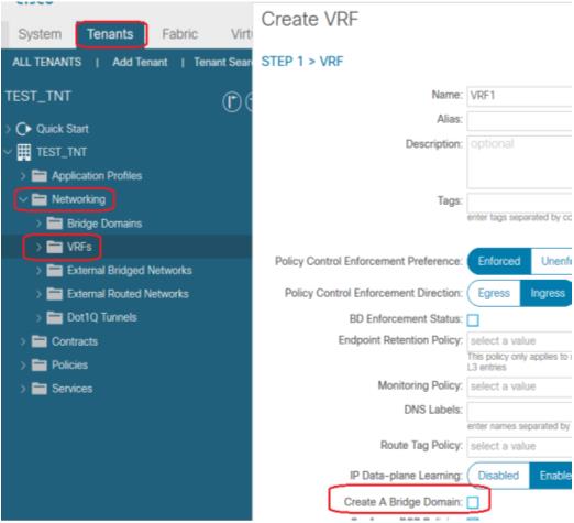
From Tenant >Tenant Name > Networking, Right click on VRFs to create VRF1. Uncheck Create A Bridge Domain option, Bridge Domain will be created later

Repeat this operation to create VRF2
10. Create Bridge Domains
From Tenant > Tenant Name > Networking, Right click on Bridge Domains to create bridge domain BD1. Assign VRF1 to BD1
Click on Next to create BD1 Subnet
- Configure the Gateway IP address on BD1. This will be the Endpoint’s gateway
- Check Advertised Externally option, this will allow BD1 subnet to be advertised through L3 Out
Repeat this operation for the other bridge domains BD2, BD3 and BD4
11. Create Application Profile
From TEST_TNT, right click on Application Profile
12. Create EPGs
From TEST_TNT > Application Profiles, right click on TEST_ApProfile to create Apllication EPGs
13. Create External Routed Networks (L3Out)
Despite each VRF is connected to R1 with two Sub Interfaces, since each VRF is connected to the same router with the same policy, only one L3Out per VRF is needed
From Tenant > TEST_TNT > Networking, Right click on External Routed Networks to create L3Out for VRF1.
- OSPF routing protocol will be enabled and configured
- Assign VRF1 and TEST_L3_Domain previously created to this L3Out
- Check Route Control Enforcement Import option, this will ensure external routes to be imported into VRF1 routing table
Repeat this operation to create VRF2 L3Out
14. Create Logical Node Profile
Logical Node Profile will be created for VRF1 and VRF2. The procedure bellow shows how to create Node Profile to associate Border Leaf (101 and 102) with VRF1 L3Out .
From Tenant > TEST_TNT > Networking > External Routed Networks > VRF1_L3Out, Right click on Logical Node Profiles to create Node Profile for VRF1 L3Out
Click on the ‘+’ sign, at the right to Nodes, to configure the Border Leaf switch (101) where this L3Out will associated; Also provide Border Leaf Router ID, the click on OK
Repeat this operation to configure Border Leaf switch (102) where the second VRF1 L3Out is associated; Also provide Border Leaf Router ID, the click on OK.
The figure bellow shows two nodes (101, 102) have been associated to VRF1_L3Out
Click on Submit
15. Create Logical Interface Profile
From Tenant > TEST_TNT > Networking > External Routed Networks > VRF1_L3Out > Logical Node Profile > VRF1_L3Out_NdProfile, Right click on Logical Interface Profiles to create Interface Profile for VRF1 L3Out
Click on Next, to configure OSPF, BFD ad HSRP profiles
Click on Next to associate Routed Interfaces, Routed Sub-interface or SVI to L3Out. In this setup,
Routed Sub-interfaces will be used.
Click on the ‘+’ sign to add Sub-Interfaces
Click OK, and repeat the operation for the Sub-Interface on Leaf node 102
Repeat this operation to create and configure Interface Profile for VRF2 L3Out
16. Create External EPG
From Tenant > TEST_TNT > Networking > External Routed Networks > VRF1_L3Out, Right click on Networks to create External EPG for VRF1 L3Out
Click on the ‘+’ sign to configure external subnet for EPG.
- External Subnets for the External EPG option (Checked by default) is much like an ACL, it defines which network is being assigned to this external EPG. An internal EPG can communicate only with this subnet (Provided, a contract is in place).In the above configuration, any external subnet is assigned to this external EPG
Repeat this operation to configure External EPG for VRF2 L3Out
17. Create Contract
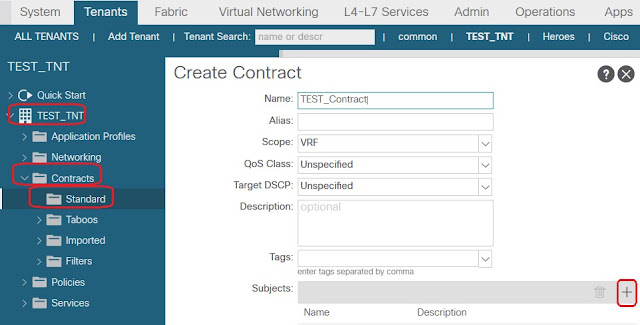
From Tenant > TEST_TNT > Contracts, right click on Standard to create a contract to allow HTTP traffic
Click on ‘+’ sign to add Subject that allow HTTP traffic
Click on Submit
18. Assign Contract to EPGs
The contract created will be
- Assigned to External EPG as Provided
- Assigned to internal EPGs as Consumer
In Tenant TEST_TNT navigate to VRF1_Ext_EPG. from policy > Contracts > Provided Contracts, click on ‘+’ sign to add the contract as Provided to External EPG
Transit Routing
By default, routes learned from one L3Out are not redistributed to another L3Out, meaning transit routing is not enabled on ACI fabric.
Back to our setup, to redistribute routes learned from VRF1_L3Out to VRF2_L3Out we have to check some checkboxes in VRF1_Ext_EPG Create subnet configuration page.
In addition to External Subnets for the External EPG option, the following options have to be enabled:
- Export Route Control Subnet option allows subnets, defined in IP Address (0.0.0.0/0 means any subnet), learned from VRF1_L3Out to be redistributed to VRF2_L3Out.
- Aggregate Export option is only available if
- Export Route Control Subnet is enabled
Quote from Cisco APIC Online Help:
Quote from Cisco APIC Online Help:
The same configuration has to be performed, in VRF2_Ext_EPG Create subnet configuration page, to export VRF2_L3Out routes to VRF1_L3Out.
Also, a contract must be configured between external EPGs, VRF1_Ext_EPG and VRF2_Ext_EPG, to allow communication between extenal hosts


Great document.
ReplyDeletevery well written! Thank you!
ReplyDeletevery good document
ReplyDeleteThanks a lot for details information along with step by step procedure, This document helps me to understand concept in the easiest way!
ReplyDeleteI love this document. Thank you...
ReplyDeleteI would like to thank you for the efforts you have made in writing this article, Its good and Informative.
ReplyDeletepega cpba
This comment has been removed by a blog administrator.
ReplyDelete